How to Extend Your Network Transmission Distance?
To face the need for long-haul, high-capacity transmission, experts come up with several DWDM projects including DWDM Mux Demux, EDFA amplifier (erbium-doped fiber amplifier) and DCM module (dispersion compensation module) to expand network capacity and enhance the signal power, which can greatly extend the optical network reach. Do you have the need to deploy a longer fiber optical transmission link? If yes, you can just build a DWDM system with the DWDM projects mentioned above. This paper will introduce three solutions that utilize these DWDM components to extend the optical network transmission distance. Hope these DWDM solutions would be useful for you.
Using DWDM Mux Demux for Long Transmission up to 50 km
DWDM technology plays an important role in building long-haul transmission system, which enables multiple signals with different wavelengths to be transmitted through only one single fiber. To build a long system with DWDM technology, the DWDM Mux Demux is an indispensable component that features low insertion loss and polarization-dependent loss. By using the DWDM Mux Demux in your network, the signal transmission distance can be extended to up to 50 km. To better know the advantage of DWDM Mux Demux, here offers an example that uses two 8 channel DWDM Mux Demux for extending the optical fiber link.
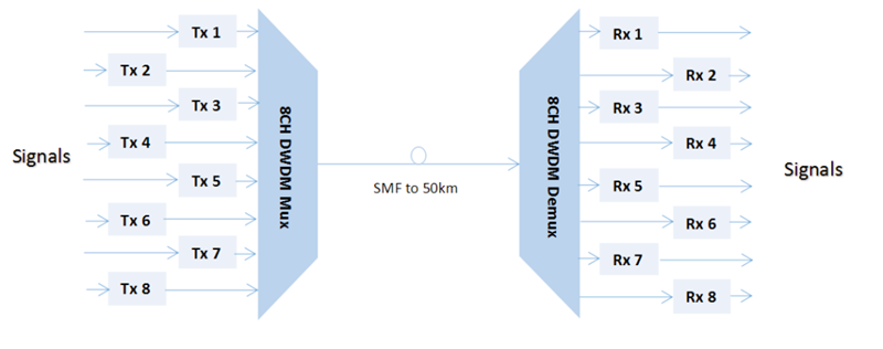
From the figure, we can learn that at the transmit side, eight kinds of signals from different fiber links are multiplexed into an integrated signal by the 8 channel DWDM Mux. Then the integrated signal is transmitted over the single mode fiber (SMF) and the maximum transmission distance can be up to 50 km. At the receiver side, the signal will be demultiplexed into individual signals with their original wavelengths by the 8 channel DWDM Demux and then transmitted to another eight different fiber links. Just by using the DWDM Mux Demux, a 50km long-haul transmission can be simply achieved.
Adding EDFA Amplifier for Transmission Longer Than 50 km
As we know, the longer the transmission distance is, the higher the fiber loss will be. Hence, except for the DWDM Mux Demux, you are suggested to add an EDFA amplifier to the long fiber link if the transmission distance is longer than 50 km. What’s the function of EDFA amplifier? It is mainly designed to amplify the signal power, which enables longer transmission. As shown in the following figure, you can learn that the only difference is the EDFA amplifier in the SMF, compared to the first solution.
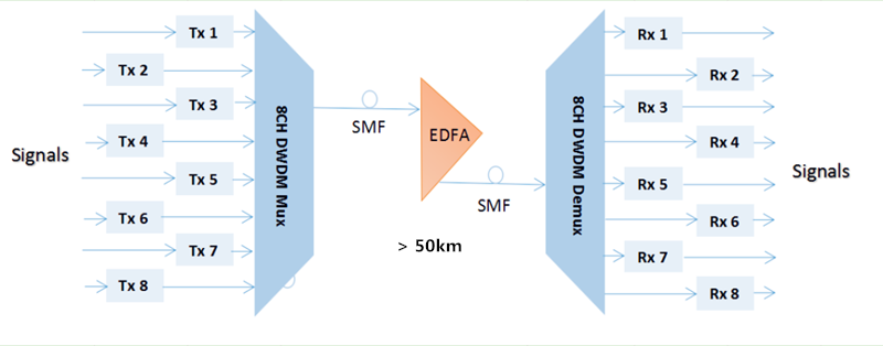
When the integrated signal multiplexed by the 8 channel DWDM Demux is transmitted over the SMF, it would become too weak in the transmission process to be transmitted. Then the EDFA amplifier should be placed there to boost the signal power, supporting the transmission longer than 50 km. Once the long transmission is realized, the signal will be also split by the 8 channel DWDM Demux, like the first solution. In short, DWDM Mux Demux and EDFA amplifier are highly suggested if you want to deploy a DWDM system longer than 50 km.
Adding DCM Module for Transmission up to 200 km
With the use of EDFA amplifier, the DWDM fiber link can be extended to 200 km. However, the signal quality is always unsatisfied due to the optical dispersion in long transmission, especially in CATV systems. To meet high requirements of the signal quality in these long transmission systems, an additional optical component, DCM module are needed in the long fiber link, as deployed in the figure below.

From the figure, we can learn it is a long-haul point-to-multipoint CATV system. To extend the transmission distance, 8 channel DWDM Mux Demux, EDFA amplifier are used. Except for that, a DCM module is added to enhance the skew signal for ensuring the whole transmission quality. With the use of DCM module, the accumulated chromatic dispersion issue is solved, without dropping and regenerating the wavelengths on the long fiber link. Thereby, a high-performance 200km system can be reached.
Conclusion
DWDM projects including DWDM Mux Demux, EDFA amplifier and DCM module are key optical components to support long-haul transmission systems. If you want to deploy a long transmission system up to 50 km, then the DWDM Mux Demux is needed. For transmission longer than 50 km, both the DWDM Mux Demux and EDFA amplifier are required for boost the signal power. But once the transmission distance is about 200 km, you should additionally add the DCM module to enhance the signal quality.
Whether to Use EDFA Amplifier in Long WDM System Or Not?
Currently, utilizing WDM technology to deploy the optical network has received widespread attentions, which enables higher capacity for data transmission. However, the technology is also limited by the transmission distance. When deploying a long WDM system, the signal power would still become weak due to the fiber loss. In order to address the issue, using EDFA amplifier to directly enhance the WDM signals would be a good choice for current and future optical network needs. The optical network combining WDM technology and EDFA module together can transmit multiple signals over the same fiber, at lengths up to a few hundred kilometers or even transoceanic distances. To better know how does EDFA amplifier work in the long WDM system, let’s learn the EDFA amplifier knowledge and analyze the performance of WDM system bonding with the EDFA module.
Introduction to EDFA Amplifier
EDFA amplifier, also referred to as erbium-doped fiber amplifier, is basically composed of a length of Erbium-doped fiber (EDF), a pump laser, and a WDM combiner. When it works, the pump laser with 980 nm or 1480 nm and the input signal around 1550 nm can be combined by the WDM combiner, then transmitted and multiplexed into the Erbium-doped fiber for signal amplification. The pump energy can be transmitted in the same direction as the signal (forward pumping), or the opposite direction to the signal (backward pumping), or both direction together. And the pump laser can also using 980 nm or 1480 nm, or both. Taking the cost, reliability and power consumption into account, the forward pumping configuration with 980nm pump laser EDFA amplifier is always the first choice to enhance the signals for a long WDM system.
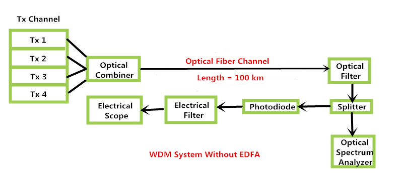
Analysis of WDM Network Without EDFA Amplifier
Before analyzing WDM network deployed with EDFA amplifier, it is necessary to know the basic configuration of an original WDM network, as shown in the figure below. We can learn that four signals from different channels are combined by the optical combiner. And then, the integrated signals are transmitted through an optical fiber. Thirdly, the signals are split into two parts by the splitter. One part passes through the optical spectrum analyzer for analyzing signals, and the other one goes through the photo detector to be converted into electrical signal and then be observed by the electrical filter and scope. However, in the process, the signal power gets highly attenuated after being transmitting at long distance.
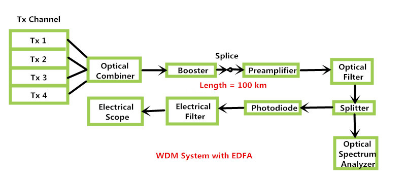
Analysis of WDM Network Using EDFA Amplifier
By using the EDFA amplifier, we can easily overcome the attenuation of long WDM network. From the following figure, we can learn that EDFA amplifiers act as booster amplifier and pre-amplifier to enhance the signal, so that system will no longer suffer from losses or attenuation. Therefore, if you need to deploy a long WDM system, it is highly recommended to deploy the EDFA amplifiers in the system that features flat gain over a large dynamic gain range, low noise, high saturation output power and stable operation with excellent transient suppression. It is an undoubtedly ideal solution with reliable performance and relatively low cost to extend the WDM network transmission distance.
Conclusion
It is well know that the signal power would be greatly attenuated when the transmission distance is long enough. Hence, when deploying a long WDM network, it is definitely necessary to use the EDFA amplifier to enhance the signal strength, allowing for the long transmission distance. As a preferable option, the EDFA amplifier with very low noise is relatively insensitive to signal polarization and easy to realize signal amplification.
Can the Hybrid CWDM-DWDM System Work for Higher Capacity?
When facing the capacity-hungry issue, have you ever hesitated over which WDM system should be choose? As the CWDM system is a more economical solution for limited expanding capacity while the expensive DWDM solution enables much higher capacity, which one should be chose is really a tough decision. In order to solve the issue, can we deploy a Hybrid CWDM-DWDM system, for not choosing a wrong solution to increase the network capacity? Thereby, both the bandwidth shortage with CWDM solution or the potential bankruptcy with DWDM solution can be avoided. Let’s seeking the answer.
Can the Hybrid CWDM-DWDM System Work?
Can the Hybrid CWDM-DWDM system work for higher network capacity? The answer is yes. In fact, it is an ideal solution for boosting the network capacity, which is designed with merging DWDM and CWDM traffic seamlessly at the optical layer, taking full use of the WDM technology. In a hybrid CWDM-DWDM system, more channels can be added to deal with the limited capacity and reach in a CWDM system. That’s to say, the hybrid CWDM-DWDM system utilizes the DWDM technology to empower CWDM system, by integrating CWDM and DWDM equipment, which offers true pay-as-you-grow capacity growth and investment protection.
In short, the hybrid CWDM-DWDM system is a simple, plug-and-play option that enables more DWDM channels interleaved with the existing CWDM channels, for transmitting more data signals. It gets the utmost out of CWDM and DWDM technologies in a single system that greatly reduces the cost, simplifies the installation and keeps the system flexibility for bigger network capacity.
How to Build a Hybrid CWDM-DWDM System?
In general, a normal complete optical connection can be simply done by using a length of fiber patch cable to connect two fiber transceivers and then separately inserting the two transceivers into the ports of two switches. While in a hybrid CWDM-DWDM system, both the CWDM Mux Demux and DWDM Mux Demux should be added offering multiple channels to multiplex and demultiplex the signals. Here offers a typical 44 channel hybrid CWDM-DWDM system information for your reference.
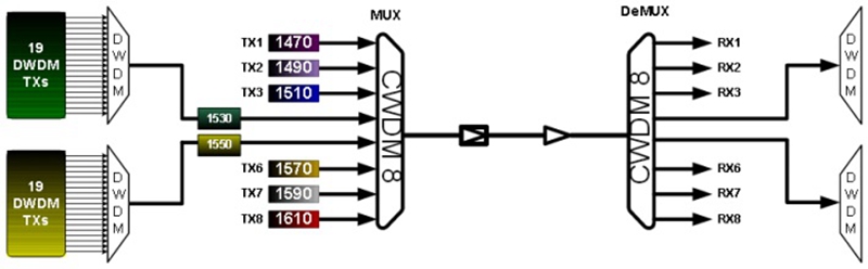
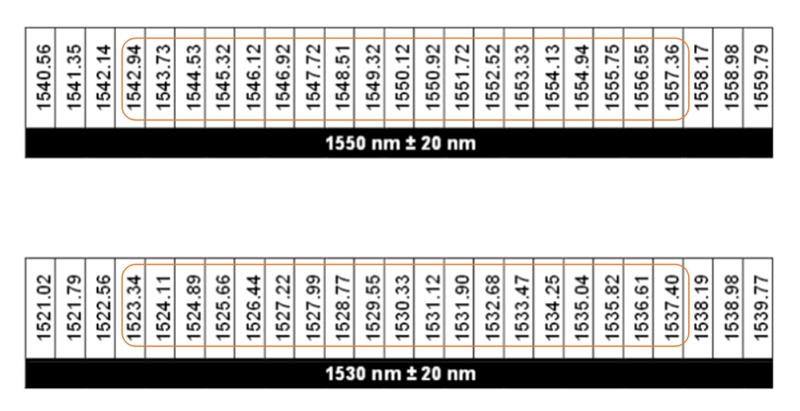
From the figure, we can learn that the original CWDM system uses two 8 channel CWDM Mux Demux with wavelengths from 1470 nm to 1610 nm (20nm channel spacing). In order to add more channels for transmitting larger data signals, two pairs of DWDM multi-channel Mux/Demux are deployed separately under the pass band of the existing CWDM filters. In principle, deploying the DWDM multi-channel Mux/Demux in the 1530nm channel can create 25 100 GHz spaced DWDM channels. However, only 19 DWDM channels circled in the following figure are suitable to be added in the hybrid CWDM-DWDM system. It is also the same to the 1550 channel. Hence, this hybrid CWDM-DWDM system totally offers 6 CWDM channels and 38 DWDM channels with less deployment cost but easier installation.
Conclusion
If you come across the capacity-hungry issue and can’t make the decision about which WDM system should be choose for increasing your network capacity, you are highly recommended to deploy a hybrid CWDM-DWDM system. As an economical and future-proofing solution, the hybrid CWDM-DWDM system can completely deal with the issue of bandwidth shortage when building a CWDM system and avoid the potential bankruptcy for a DWDM system. You can just deploy a CWDM system first. Once the capacity the CWDM system offers can’t meet your requirement, you can add DWDM equipment in for more channels to transmit signals. All in all, the hybrid CWDM-DWDM system is an ideal choice that not only costs less for deployment but keeps the flexibility to increase the network capacity.
Choose the Right SFP+ Transceivers for CWDM Mux Demux
Nowadays, CWDM technology is very popularly used as a easy and economical way to extend the network capacity by carrying several signals with different wavelengths through a signal fiber. If your network capacity is not enough for your daily use, deploying a CWDM system is an ideal choice for you. As the CWDM Mux Demux should be finally linked with the switches in a completed CWDM system, the fiber patch cable and 10G CWDM SFP+ transceiver are required to finish the whole CWDM link. Hence, this paper will mainly introduce the CWDM Mux Demux and choose the right CWDM SFP+ transceivers for the CWDM Mux Demux, which may be helpful for you to fast build a CWDM system.
CWDM Mux Demux–Key Component for CWDM System
CWDM Mux Demux is a key component for CWDM system, which should work in pairs. As an optical module, it can act as a multiplexer or demultiplexer at either end of the fiber cable. This kind of optical Mux Demux is much easier to use than the DWDM Mux Demux, but can not support the network as long as that of the DWDM Mux Demux. In general, it can offers several kinds of wavelengths, usually from 1270nm to 1610nm (20nm spacing), to support the signal transmission at lengths up to 80 km. Meanwhile, the CWDM Mux Demux can be designed with 4 channels, 8 channels, 9 channels, 16 channels and 18 channels for transmitting different amount of signals. To better know how does this kind of WDM Mux work, the following figure offers a reliable 4 channel CWDM Mux Demux duplex transmission design.

From the figure above, we can learn that two CWDM Mux Demux are connected by a length of duplex patch cable, and they are designed with four channels multiplexing the 1470nm, 1490nm, 1510nm and 1530nm over the same fiber. To complete the transmission link, four pairs of CWDM SFP+ transceivers with 1470nm, 1490nm, 1510nm and 1530nm TX and RX should be separately inserted into the ports of these two WDM Mux Demux. When the CWDM system works, the four different signals from the left to the right will be multiplexed in the CWDM Mux, transmitted over the duplex fiber and demultiplexed in the CWDM Demux, and vice versa for the signals from the right to the left.
How to Choose the CWDM SFP+ Transceivers for CWDM Mux Demux?
As mentioned above, the CWDM SFP+ transceivers are required for building a CWDM system which should be correctly inserted into the SFP+ ports of the CWDM Mux Demux. Thereby, here offers three factors that should be taken into consideration when choosing the CWDM SFP+ transceivers for the CWDM Mux Demux.
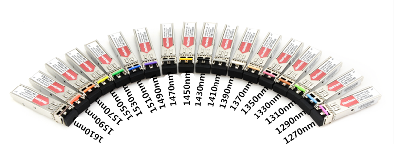
The first factor is the working wavelengths of the CWDM SFP+ transceivers. In order to ensure the CWDM system performance, the SFP+ transceiver working wavelengths should be the same to the SFP+ ports of the CWDM Mux Demux. Just like the first figure, when the working wavelengths of the first pair of CWDM SFP+ transceivers are 1470 nm, the first ports of the two CWDM Mux Demux should be also 1470 nm, so that the signal with 1470 nm can be successfully transmitted in the CWDM system. As the CWDM working wavelengths are available from 1270 nm to 1610 nm and the channel spacing is 20 nm, there are 18 kinds of working wavelengths for CWDM SFP+ transceivers, as shown in the following figure.
The second factor is the compatibility of the CWDM SFP+ transceivers. As the third party transceivers are more cost effective than the original one, the former kinds are always the choices for most users. However, the users are always unassured about the quality and compatibility of the third party transceivers for their low price. Here FS.COM is recommendable who offers the CWDM SFP+ transceivers fully tested on most famous original brand switches like Cisco, Brocade, Juniper and Arista. FS.COM CWDM SFP+ transceivers are less expensive but can perform as well as the original branded transceivers, without the compatible issue.
The third factor is the transmission distance the CWDM SFP+ transceivers can support. Although the CWDM system can not support the transmission as long as the DWDM one, it still can reach the lengths 80 km. At present, 10G CWDM SFP+ transceiver can be available at lengths of 20km, 40km, 60km, 80km or even longer on the market. Hence, you can also choose the CWDM SFP+ transceivers according to the transmission distance you system needs.
Conclusion
Building a CWDM system for carrying more data signals is a good choice if the existing network has insufficient capacity. To ensure the performance of the whole CWDM link, it is necessasry to choose the right CWDM SFP+ transceivers for the CWDM Mux Demux. From this paper, it can be concluded that there are mainly three factors, the working wavelength, the compatible issue and the transmission distance the CWDM SFP+ supports, should be taken into account when making the decision about which kind of CWDM SFP+ should be selected for the CWDM Mux Demux.
Single Fiber Solutions for CWDM and DWDM Networks
It is well known that there are two transmission ways for fiber optical network, single fiber transmission and dual fiber transmission. From the name, it is easy to learn that the fiber amount is the main difference of these two transmission ways. For the dual fiber transmission, there should be totally two optical fibers, one for transmitting signals, and the other for receiving signals. But for the single fiber transmission, it only requires one optical fiber that can transmit and receive signals at the same time. This feature makes the network deployment easier and the network deployment cost lower than that of dual fiber one, especially in WDM network deployment. In this paper, it will mainly introduce the single fiber solution and its applications in CWDM and DWDM networks.
Single Fiber Solution
Single fiber solution can be also called bidirectional (BiDi) solution designed for carrying signals in both sides of one optical fiber simultaneously. When the single fiber network runs, the signals transmitted from the two sides feature different wavelengths to ensure the dual way transmission. Compared to the dual fiber network, the easy-to-deploy single fiber network would be a good choice for those who have limited budgets but need for bigger network capacity. As for its application, it is very popularly used in Point to Point, Ring or linear Add and Drop, where installing new fibers is impracticable or uneconomical. It can be also used for promoting the reliability of an existing dual fiber network, in which there are one optical fiber for work and the other one for protection.
Single Fiber CWDM Network
The single fiber CWDM network enables the signals with different wavelengths to be transmitted through a signal fiber, which results in a network capacity boost in metro and access networks. As each signal beam can be carried via different channel independently, the different data rates and protocols (T1, T3, Ethernet, Serial, etc) can be transmitted for the different users or applications. To better know how does the single fiber CWDM network work, here offers a figure that shows a 8 channel single fiber CWDM network design.
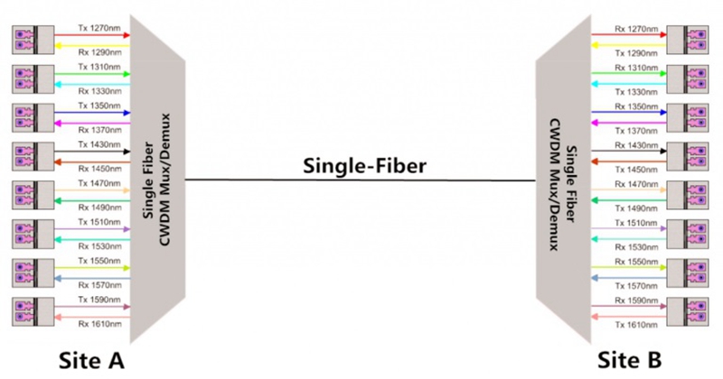
From the figure, we can learn there are two 8 channel CWDM Mux Demux connected by a single fiber for transmitting 16 signals with different wavelengths and the 16 wavelengths are divided into 8 pairs for bidirectional transmission. On the site A, 8 wavelengths are used for transmitting signals and others for receiving signals. While on the site B, the wavelengths for the TX and RX on the CWDM Mux Demux are all reversed to ensure the performance of the single fiber CWDM network. For instance, the 1270 nm on the site A is the first transmitting wavelength but the first receiving wavelength on the site B. As a result, the signal with 1270 nm can be totally transmitted from site A to site B via the single fiber.
Single Fiber DWDM Network
The single fiber DWDM network also takes full use of the wavelength division multiplexing technology that can greatly expand the capacity over the existing optical network, especially for the long transmission network. Compared to the CWDM one, it can be designed with more channels for larger data signals and can support the network with a much longer distance. What’s more, if the transmission distance is too long, the optical amplifier can be used to enhance the signals. On the other hand, all these advantage makes the cost to deploy a single fiber DWDM network much higher than the CWDM one. Besides, here offers the figure of a single fiber DWDM network design for your reference.
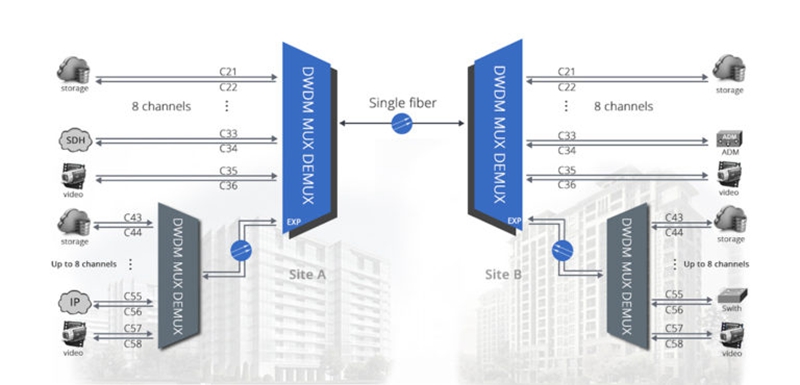
The figure shows a complicated a single fiber DWDM network design that uses two 8 channel DWDM Mux Demux in the main link for single fiber transmission. As for the wavelength feature of the TX and RX for the ports on the DWDM Mux Demux, it is similar to the CWDM one, but the channel spacing is denser. What’s more, except for the existing channels in the main single fiber DWDM link, there can be more channels added into the expansion port of the link for carrying larger data signals. In short, although the cost for deploying single fiber DWDM network is so expensive, it is still a good solution that can make full use of the fiber link to transmit more signals at a much longer distance.
Conclusion
Undoubtedly, the single fiber WDM solution is an ideal choice for those who have limited budgets but need for bigger network capacity. As there are two single fiber WDM solutions available, which one to choose just depends on the network need and budget. The single fiber CWDM network would be more economical but can not transmit as much signals as the DWDM one can, while the DWDM is highly recommended for large and long transmission that would cost more.
Single Fiber CWDM Network Overview
When designing the fiber optical network, we used to choose the duplex fiber cable as the first choice to finish the dual-way transmission, which transmits the dual-way signals via two separate simplex cables from the opposite sides. However, in some typical dual-way applications like working with BiDi fiber optic transceiver, the simplex fiber cable is required to transmit the dual-way signals respectively over only one fiber cable by using two different wavelengths that has a more complicated working principle than the duplex one. If we want to deploy a single fiber CWDM network, the basic principle is similar to simplex fiber cable but would be much more complicated, which will be explained detailedly in this post.
What Is the Single Fiber CWDM Network?
Single fiber CWDM network is a special kind of WDM network that can greatly increase the network capacity by combining and transmitting several pairs of signals with different wavelengths over a single fiber, with the aim of supporting several dual-way connections at the same time. To deploy the single fiber CWDM network, a pair of single fiber CWDM multi-channel Mux/Demux and several pairs of CWDM transceivers are needed. When the single fiber CWDM network works, the two single fiber Mux Demux require different wavelengths for each pair of dual-way transmission, which is very different from the dual fiber Mux Demux using the same wavelength for a pair of dual-way transmission. That’s to say, there are only four different wavelengths used for 4-channel dual fiber CWDM Mux Demux, but eight different wavelengths divided into four pairs for 4-channel single fiber CWDM Mux Demux.
How Does the Single Fiber CWDM Network Work?
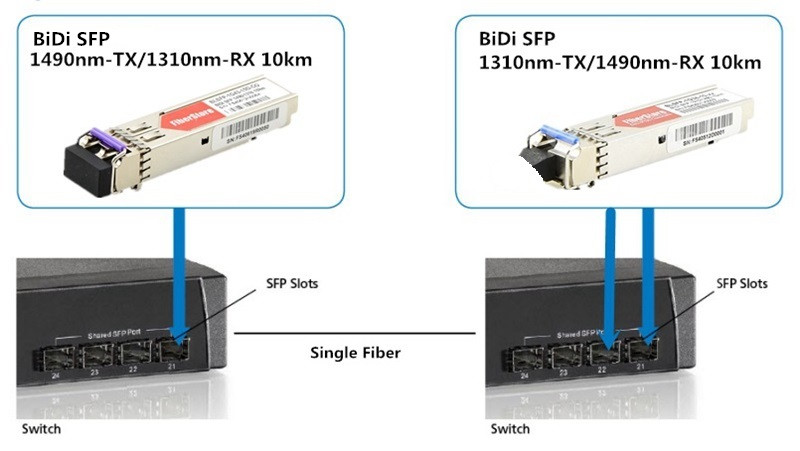
Before talking about the single fiber CWDM network, let’s take a simple BiDi network as an example first. In the BiDi network, only one simplex fiber cable and a pair of BiDi fiber optic transceivers are required to finish the dual-way connection. In details, the two BiDi fiber optic transceivers should be almost the same but has reversed wavelengths for TX and RX. For instance, if one transceiver with 1490nm for TX and 1310nm for RX is installed in one end of the fiber link, the other one in the opposite end should use 1310nm for TX and 1490nm for RX, as shown in the following figure. Hence, the dual-way signals with two different wavelengths can be transmitted over only one fiber cable.
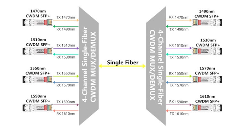
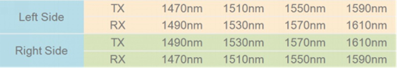
As for the single fiber CWDM network, its basic principle is similar to the BiDi network but would be much more complicated, which can be also learned from the following figure. In the figure, there are two 4-channel single fiber CWDM Mux Demux connected to each ends of the single fiber, and four pairs of CWDM SFP+ transceivers designed with eight different wavelengths, totally achieving the 4-channel single fiber CWDM network. It is easily to learn that these eight different wavelengths are divide into four pairs and each pair has the complete reversed TX and RX. For instance, the first pair of CWDM transceivers consist of a transceiver with 1490nm for TX and 1310nm for RX in the left side and a transceiver with 1490nm for TX and 1310nm for RX in the right side, thereby a pair of dual-way signals with two different wavelengths will be transmitted through the first channel. To better understand how does the single fiber CWDM network work, the following table lists the eight ports with four pairs of wavelengths for TX and RX that are all reversed to ensure the dual-way transmission.
Conclusion
The single fiber CWDM network can greatly increase the network capacity for transmitting larger dual-way data signals, which is able to combine several pairs of signals with different wavelengths into an integrated signal and carry it through a single fiber. To build a smooth single fiber CWDM network, you should firstly install the CWDM fiber optic transceivers into two switches and then connect them into the channel ports of the two single fiber CWDM Mux Demux, finally use a single-mode simplex fiber cable to link the two CWDM Mux Demux together. Besides, to ensure the performance of the single fiber CWDM network, there are some important factors like light loss, transmission distance, and optical signal dropping and adding should also be taken into consideration.
The Most Economical QSFP28 AOC and Switch Solution for 100G Network
Nowadays, most users choose to deploy 10G and 40G network that perform highly and efficiently in their systems. It cannot be denied that the bandwidth and capacity the 10G and 40G network provide are enough for their needs at present. However, due to the fast developing Ethernet network technology, the scale and traffic of Internet is rapidly expanding that will make the 10G and 40G network gradually obsolete and unsuitable for data centers, especially for the large-scale ones. Along with this trend, there is no doubt that the 100G network will become the mainstream in the near future. Are you now ready for the 100G network? Or still hesitating because of the high cost? In this paper, it will introduce some 100G QSFP28 AOC and switch solutions that can help you seek the most economical one to upgrade your system from 10G/40G to 100G.
100G QSFP28 AOC Solutions
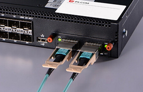
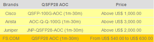
QSFP28 AOC is a cost effective cable solution for 100G short distance transmission that consists of an OM4 multimode cable and two QSFP28 connectors, supporting 100G QSFP28 standards and compliant to the QSFP MSA (multi-source agreement). The length of the cable is usually available from 1 to 30 meters and its two QSFP28 connectors are fitted at each end of the OM4 multimode cable, very convenient for inserting into and removing from 100G QSFP28 ports. In data center, the QSFP28 AOC is really a low power alternative for 100G short distance transmission, which is highly recommended for the simplified intra rack and inter rack configurations. To seek the most economical QSFP28 AOC solution, the figure below shows the prices of several famous brands of QSFP28 AOC for your reference.
100G Switch Solutions
100G switch is an improved kind of network device designed for data center that offers the signal lane for any two 100G network nodes inserted into its ports. With the popularity of 100G network, it can be also available on many famous fiber optic manufactures like Cisco, Arista, Juniper, as well as the fiber optic manufacture FS.COM. With the aim of looking for a more economical 100G switch solution, the following will mainly introduce Cisco Nexus 3232C, Arista 7500R, Juniper QFX5110 and FS.COM S5850-48S2Q4C, both of which are fitted with QSFP28 ports to support QSFP28 AOCs.
The first type of switch–Cisco Nexus 3232C is a typical kind of low latency and high-performance 100G switch that can not only fulfill our current network needs but also suit for future applications such as big data, cloud and virtualization. And all its 100G QSFP28 ports can operate at 10, 25, 40, 50 and 100 GbE. The second type–Arista 7500R switch, including 7500R-36CQ, 7500R-36Q and 7500R-48S2CQ, is designed to lower power per 100GbE port and produce more reliable and dense network, which are available in a compact system design of 12, 8 and 4 slot. The third type–Juniper QFX5110 can be simply divided into QFX5110-48S and QFX5110-32Q, both of which have 100G QSFP28 ports to support QSFP28 AOC. All these three kinds of 100G switches are very expensive which can be learned from the following figure.
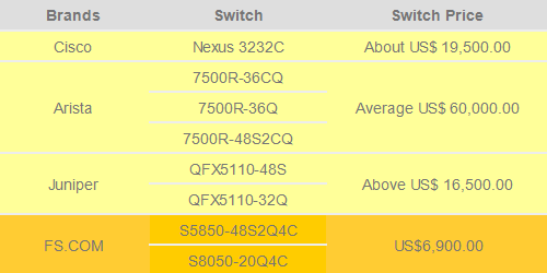
Compared to the previous three types, 100G switches like S5850-48S2Q4C and S5850-20Q4C provided by FS.COM can be available at a much lower cost. In details, the S5850-48S2Q4C has 48x10GbE SFP+ ports, 2x40GbE QSFP+ ports and 4x100GbE QSFP28 ports, while the S8050-20Q4C has 2x40GbE QSFP+ ports and 4x100GbE QSFP28 ports. Both of them are the cost effective switch solutions for building 100G network.
Discussion and Conclusion
From the text above, it can be easily learned that using Arista QSFP28 AOC and switch to deploy the 100G network would cost the most that can be as high as US$ 63,000.00, while the QSFP28 AOC and switch solution provided by FS.COM would be the most economical one, available at a quite low cost usually from US$ 7,440.00 to US$ 7,530.00. Considering that, you are recommendable to use the FS.COM QSFP28 AOC and switch solution for building your 100G network. If you have already had the switch like Cisco, Arista or Juniper, you are also suggested to choose FS.COM compatible QSFP28 AOC that has been tested to assure 100% compatibility, as a much more cost-effective cable solution.