An Guide on MTP Fiber Connector
MTP, short for Multi-fiber Termination Push-on, is the standardized terminating end of a multi-fiber cable which can support for all practical intents and purposes up to 24 fiber strands per connector. The MTP fiber connector is an improved, proprietary version of the standard MPO cable connector in respect to attenuation and reflection, but it adopts the same form-factor and multiplex push-pul coupling type. Developed by US Conec, the MTP connector has been enhanced in overall performance by implementing structural improvements and higher quality materials.
For What Reason to Choose an MTP Fiber Connector?
As the MTP fiber connector significantly reduces the amount of insertion loss experienced when mating connectors. It allows optical fiber networks run much more efficiently, especially at high data transfer rates of 40G and 100G. MTP is therefore the best connector for cables to be utilized in environments which require the absolute best performance currently available.

MTP cable and connector have also gained popularity with installers. Due to being able to route dozens of individual fiber strands using a single lightweight fiber cable assembly. Each MTP connector is able to host 8 to 144 individual fibers within a single connector body. Although 8, 12 and 24 fibers are the most commonly used in today’s communication and datacenter industry. These high density and high performance optical connectors are able to reduce the overall bulk and cost associated with installing large quantities of individual fiber patch panels. As a result, MTP cable allows a network to be up and running in minimum time.
What Is the Polarity for MTP Cable Connector?
MTP polarity refers to the order and sequence of the internal fiber strands and their position within the connector in which they are terminated. The polarity of an MTP cable connector determines which strand is used for transmitting or receiving data and therefore its compatibility with networking hardware like optical transceivers, switches and patch panels. Typically referred to as Method A, B, C and Z, the polarity of connectors can get rather complicated. For more information on this please read our MTP polarity guide. MTP 8 and 12 fiber cable assemblies feature the unique ability of having their polarities swapped from A to B or vice versa. This to keep downtime to a minimum and improves a cable re usability in the event of network restructuring.
MTP Cable Connector Gender and Color
Each MTP connector is either of the Pinned (male) or Non-Pinned (female) variety. A connector in a fixed location is a jack and a movable connector is a plug. Pinned (male) connectors are most commonly used at end points. Such as in a fiber patch panel or fiber cassette for redistribution. Our connectors are available in a variety of distinct colors. These vivid selections allow a network installer to easily identify which mode and polish is contained within the fiber cable assembly and reduces downtime due to misconfigured equipment.
Summary
Regardless of whatever technology you’re working with, it is worth the cost to make MTP cables part of your data center build-out, and embrace the advantage of the time savings, space efficiencies, and simplicity synonymous that come with the MTP technology.
Introduction to MTP Connector and MPO Connector
With an increasing demand for faster data transfer speed, the capacity to transfer data as efficiently as possible remains the main force in today’s communication age. Since the backbone of most modern digital information systems is supported by fiber optic networks, there is a growing focus upon the MPO fiber connector and MTP fiber connector.
What Are MPO and MTP Connectors?
MPO is the industry acronym for “multi-fibre push on.” Originally created in the late 20th century, MPO connector is the first generation of clip clamping multi-core optic fiber connector, which developed by the Japan NTT to easily interconnect multiple fiber strands and transfer an ever increasing amount of data.
While MTP is a registered trademark of US Conec, marketed as a “high performance MPO connector with multiple engineered product enhancements to improve optical and mechanical performance when compared to generic MPO connectors.” Both MTP connector and MPO connector are available with standard or elite / low loss options. The picture below shows the transmission of a 24-fiber MTP fiber connector.

What Makes the MTP Connector Superior to MPO?
The MTP connector has features and benefits that are not available on generic MPO connectors. Some of the key distinctions include:
1. The MTP connector housing is removable. This feature allows the customer to re-work and re-polish the MT ferrule, change the gender after assembly or even in the field and scan the ferrule interferometrically after assembly.
2. The MTP connector offers ferrule float to improve mechanical performance. This allows two mated ferruled to maintain physical contact while under an applied load.
3. The MTP connector uses tightly held tolerance stainless steel guide pin tips with an elliptical shape. The elliptical shaped guide pin tips improves guidance and reduces guide hole wear.
4. The MTP connector has a metal pin clamp with features for centering the push spring. This can help eliminates lost pins and center spring force.
5. The MTP connector spring design maximizes ribbon clearance for twelve fiber and multi-fiber ribbon applications to prevent fiber damage.
6. The MTP connector is offered with four standard variations of strain relief boots to meet a wide array of applications. The short boot reduces the footprint by 45%, making it an ideal choice for use in space limited applications.
Summary
Low loss MTP connector and MPO connector deliver the performance and reliability needed in today’s demanding high-speed broadband and data networks. Many suppliers like FS offers an extensive line of high-density MPO/MTP fiber connector products, including jumpers, fanouts, pigtails and connectorized cable. When you need a high-performance fiber optic connectivity solution, you can look to their products featuring the MPO/MTP connector and choose freely.
What is Polarization-Maintaining Fiber (PM Fiber)
Polarization-maintaining optical fiber (PM fiber) is a special optical fiber with strong built-in birefringence, which can preserve the properly oriented linear polarization of an input beam. Usually, optical fibers will exhibit some degree of birefringence even when they have a circularly symmetric design, because there always has some mechanical stress or other effect which can break the symmetry. The polarization of light propagating in the fiber gradually changes in an uncontrolled (and wavelength-dependent) way, which also depends on any bending of the fiber and on its temperature. This polarization maintaining feature is extremely important for some fiber optic components such as external modulators that require a polarized light input. So PM fiber is used in special applications where preserving polarization is essential. The following text will let you know more information about PM fiber.
Principle of PM fiber
Provided that the polarization of light launched into the fiber is aligned with one of the birefringent axes, this polarization state will be preserved even if the fiber is bent. The physical principle behind this can be understood as coherent mode coupling. The propagation constants of the two polarization modes are different because of the strong birefringence, so that the relative phase of this co-propagating mode rapidly drifts away. If this difference is large enough, the usual disturbances in the fiber are too slowly varying to do effective mode coupling.
Ways of Realizing PM Fiber

The above picture shows the three types of PM fiber. These optical fibers contain a feature that is not seen in other fiber types. Besides the fiber core, there are stress rods in the fibers. Panda PM fiber has two circles of stress rods, elliptical-clad PM fiber has a elliptical clad, and the Bow-Tie type PM fiber has two bow-ties. Just as the name implies, these stress rods create stress in the core of the fiber so that the transmission of only one polarization plane of light is favored.
PANDA fiber is a telecom fiber. Its attenuation and mode-field diameter were well matched to those of single mode telecom fibers. Bow-tie fiber was invented in the early 1980s as a sensor fiber, and until today, bow-tie fibers are still typically used in sensor applications.
Applications of PM Fiber
- PM optical fibers are used in special applications, such as fiber optic sensing, interferometry and slab dielectric wave-guides. And they are also used in telecommunication for the connection between a source laser and a modulator, because the modulator needs polarized light as input.
- They may also be used in transmission applications where the polarization plane of the optical signal is important, such as transmission lines for optical sensors and coupling for optical electrical integrated circuits.
- PM fibers are used in lithium niobate modulators, Raman amplifiers, and other polarization sensitive systems to maintain the polarization of the incoming light and keep cross-coupling between polarization modes at a minimum.
Although PM fibers are widely used in various applications, they are rarely used for long-distance transmission, because they are expensive and have higher attenuation than single mode fiber. But they are expected to be used in coherent optical transmission systems or long distance bidirectional optical transmission systems.
Conclusion
PM optical fibers are widely used in polarization sensitive fiber optical systems for transmission of light requires the PM state to be maintained. FS.COM provides PM fiber cables with several different wavelengths with high extinction ratio, low insertion loss and long term reliability. They would be your good choice!
Analysis of Power Budget and Link Distance in CWDM System
It can’t be denied that CWDM technology is a cost effective method to increase the capacity in the existing system, which can give different wavelengths to multiple optical signals and multiplex them for transmission through only one single fiber. Different from the DWDM system, the network using CWDM technology are deployed by passive components like passive CWDM Mux Demux, without the need of additional power, which makes CWDM system more commonly used. Do you also plan to build a CWDM system? If yes, you can check the following information for reference, which mainly analyzes the optical power budget in a CWDM system and calculates the CWDM link distance according to the power budget for smoothly deploying a CWDM system.
What’s Optical Power Budget?
Before deploying an optical network, it is very essential to calculate the optical power budget for better deployment. What’s optical power budget? It is just the amount of light available to make a successful fiber connection which can be calculated by analyzing the original output power of the transmitter and the required input power of the receiver. In details, we should firstly learn the optical power that is emitted by the source (also referred to Transmit Power) and the required power of the detector (also called Receiver Sensitivity). Using the first data to subtract the second one, you’ll get the data of the optical power budget which greatly determines the performance of the whole network link.
Here is the equation: Optical Power Budget = Transmit Power - Receiver Sensitivity.
How to Get the Optical Power Budget in a CWDM System?
To estimate the link distance supported by a CWDM system, the optical power budget should be calculated first, which can greatly determine the CWDM link distance. Here will show you a basic CWDM system under an ideal condition to clearly illustrate how to get the optical power budget. In this basic CWDM system, there is a optical transmitter which transmit power is -2 dBm and a optical receiver with -25 dBm receiver sensitivity. Hence, the optical power budget is 23 dB, as shown in the following equation.
Optical Power Budget = Tx Power - Rx Sensitivity = -2 dBm - (-25 dBm) = 23 dB
However, the mentioned CWDM system is just under an ideal condition without loss caused by the signal transmission. In a normal CWDM system, there are many components like passive CWDM Mux Demux, CWDM transceiver inserted. All these components cause insertion loss once they are inserted into the CWDM link. Therefore, when doing the optical power budget, all the loss should be taken into account for calculating the power budget exactly.
Here is more exact equation: Power Budget = Tx Power - Rx Sensitivity - Loss
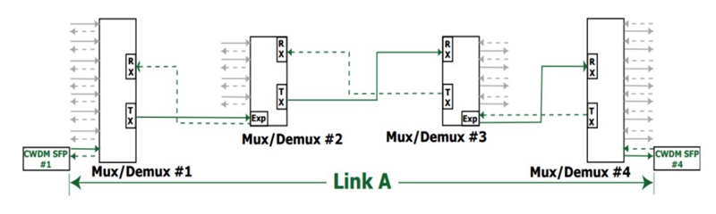
To get the real power budget of a CWDM system, here offers a simple CWDM link which uses the -2 dBm optical transmitter, -25 dBm optical receiver and four passive CWDM Mux Demux with low insertion loss. Both the stable 4 channel CWDM Mux and stable 4 channel CWDM Demux in the link have 2.0 dB insertion loss, and other two are 8 channel ones feature 2.5dB insertion loss separately, as shown in the figure below. As a result, the total loss caused by the four passive CWDM Mux Demux is 9 dB, resulted from 2.5 dB + 2.0 dB+2.5 dB + 2.0 dB. Then we can get the total power budget, 14 dB. The calculation process is: Power Budget = Tx Power - Rx Sensitivity - Loss = -2 dBm - (-25 dBm) - 9 dB = 14 dB
How to Calculate the Link Distance in the CWDM System?
After knowing the optical power budget, let’s calculate the link distance of the CWDM system according to the following equation: Link Distance = Optical Power Budget/Fiber Attenuation. As there may be some other power loss caused by the factors that we didn’t consider like fiber aging, temperature and poor splice, we often subtract 2 dB buffer from the total optical power budget. Meanwhile, the fiber attenuation is changeable according to the wavelength, usually varying from 0.2 to 0.35 dB/km. In this case, we’ll use 0.35 dB/km as a typical data. Then we can get the link distance is about 34 km. The calculation process is Link Distance = Optical Power Budget/Fiber Attenuation = (14 dB- 2 dB)/0.35 dB/km.
Conclusion
This paper intends to illustrate how to calculate the optical power budget and estimate the link distance of a CWDM system according to the optical power budget, which allows for better budget of deploying the CWDM system and eliminates the unwanted or unnecessary issues which may happen in the system deployment. Besides, if you want to make a cost effective CWDM system, you are suggested to buy CWDM components like cheap passive CWDM Mux Demux, CWDM transceivers from FS.COM, which are of good price and quality.
What Can CATV Systems Benefit from EDFA Optical Amplifiers?
As long-distance transmissions are always required in the CATV systems, it is very necessary to make the quality of visual and audio signals in high levels after the long transmissions, so that the performance of the CATV systems can be ensured. To serve this aim, the CATV EDFA optical amplifiers are come up with and widely used in the CATV systems. Why the EDFA optical amplifier is needed in CATV system? How does it work for the long CATV application? The following text will give you the answers and simply introduce two typical CATV EDFA amplifier applications for your reference.
What’s CATV EDFA Amplifier?
CATV EDFA is a kind of optical amplifier, most commonly used in the long-haul CATV system for boosting the damped CATV signals, with the aim of compensating the signal loss. Since it mostly works as booster optical amplifier in the CATV system, so that it can be also called CATV booster amplifier. By utilizing the CATV EDFA optical amplifier, the CATV signals can be enhanced to meet the system requirement and then be sent to the users. However, when the signal power is improved by the CATV EDFA, the noise existing in the transmission link would also boosted and some return loss would also occur at the same time. Considering that, it is very necessary to choose quality CATV EDFA optical amplifier for ensuring the performance of CATV system, even if it may be cost a little higher than common optical amplifier.
Why CATV EDFA Optical Amplifier is Used?
CATV is a multi-channel TV system transmitting visual and audio signals from digital or analog television and radio channel to many users via fiber or copper patch cable. As the signals should be finally separated by optical splitter to serve more than one users and many loss has occurred in the long transmission, the overall speed and quality of the CATV signals would become too weak to meet the receiver requirements. Under this condition, the CATV EDFA optical amplifier is very essential for CATV system with the function of amplifying CATV signals and giving high performance systems to the users.
How Does CATV EDFA Work for Long CATV Applications?
A long CATV system is always composed of head end, transmitter, receiver, CATV booster amplifier and optical splitter. When the system runs, the CATV signals are provided by the head end, and need to be split into several signals by the optical splitter to serve the users. When the signals pass through the optical splitter, the signal power would be in a very low level. Hence, the CATV EDFA optical amplifier should be deployed after the receiver to improve the signal power, and the users can finally receive quality signals.
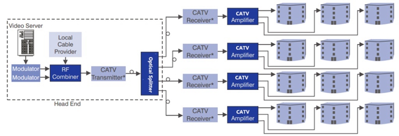
From the figure above, we can learn a simple point-to-multipoint CATV network design as mentioned above. The CATV signals are provided by the RF combiner and should be connected with four receivers by the optical splitter. In order to compensating the signal loss caused by the optical splitter, CATV EDFA optical amplifier is required before sending the weak signals to the users.
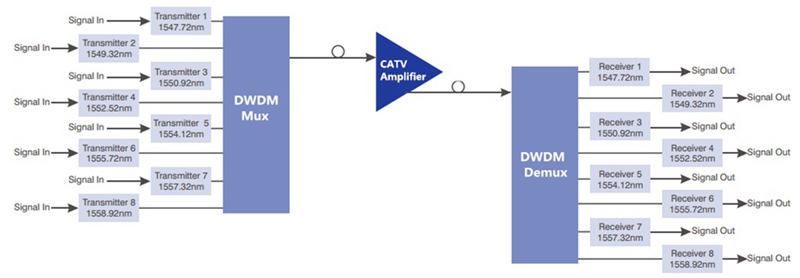
Except for this simple kind of CATV network using CATV EDFA optical amplifier, here also offers a complex CATV network, as designed in the figure below. In this CATV network, the CATV EDFA optical amplifier is deploy behind the 8 channel DWDM Mux Demux to amplify the signals while the 8 channel DWDM Mux Demux allows for higher capacity transmission. Hence, a long CATV network with big capacity can be achieved.
Conclusion
When deploying a long CATV system, we should pay attention to the loss caused by long transmission distance and CATV components. When the loss is very high, CATV EDFA optical amplifier would be an ideal device deployed in the long CATV system for improving the quality of CATV signals, so that the users can receive high speed and reliability of the services.
EDFA Amplifiers for Building Long-haul DWDM Networks
Clearly different from the traditional repeater, the EDFA amplifier doesn’t need to convert the optical signals into electrical ones, then make the electrical amplification and finally convert the amplified electrical signals into amplified optical signals again. It is an optical amplifier that can directly enhance the optical signals without making additional conversion. By using the EDFA optical amplifier, the attenuated signal power can be amplified into strong signal level to meet the requirement of the long-haul applications, especially the long-haul DWDM networks. To better understand the function of EDFA amplifier, the following will mainly study the working principle of EDFA amplifier works and illustrate how to use it to build the long DWDM network.
What’s the Working Principle of EDFA Amplifier?
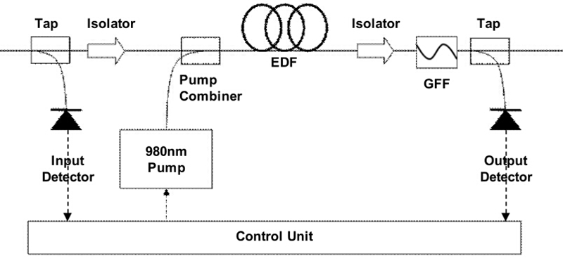
From the figure below, we can learn the basic configuration of the EDFA amplifier, mainly composed of a length of EDF (erbium doped fiber), a pump laser with 980 nm or 1480 nm, a pump combiner and a simple WDM system. When the attenuated signals around 1550 nm pass through an EDFA amplifier, a pump laser will be generated. Then the DWDM signals and pump laser will be combined by the pump combiner. When they come into the EDF together, the wavelengths of signals and pump laser will be multiplexed and the interaction with the doping ions would enhance the signal power into high level. Thereby, a longer DWDM transmission can be reached.
How to Use EDFA Amplifier for Long DWDM network?
In a long DWDM network, the EDFA amplifier can be put in three different places with different aims. Firstly, we can put it in the transmitter side of the DWDM link to offer high input signal power, so that the DWDM fiber link can be extended. If the EDFA amplifier is deployed in this place, we can also call it EDFA optical booster amplifier. Secondly, we can also place the EDFA amplifier in the receiver side of the DWDM link as optical preamplifier, hence the output signal power can be boosted to meet the necessary receiver level. Finally, when the fiber loss in the transmission process is too high to support the long DWDM network, we can deploy the EDFA amplifier in any intermediate point along the long fiber link to compensate the fiber loss. And this time, we can call it EDFA optical in-line amplifier.
Analysis of Practical Long DWDM Cases with EDFA Amplifiers
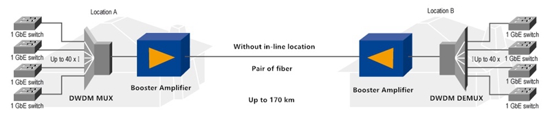
Case One: in this case, EDFA optical booster amplifiers are deployed at both transmitter sides of the dual-way DWDM links. We can learn it from the figure below. Two 40 channel DWDM Mux Demux are deployed to multiplex 40 1G signals. Then the two integrated 40G signals from both sides are enhanced by the booster amplifier and can be transmitted up to 170 km over each single fiber.
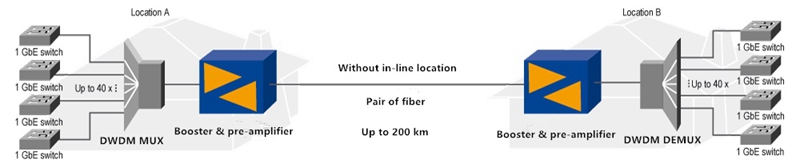
Case Two: as shown in the following figure, except for the booster amplifiers, EDFA optical optical preamplifiers are also placed at both receiver sides of the dual-way DWDM links. By adding the optical preamplifiers to the CWDM link, the transmission distance is finally extended from 170 km to 200 km.
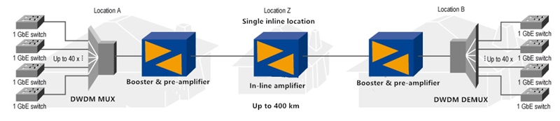
Case Three: it is highly noted from the following figure that the DWDM transmission distance can be up to 400 km. How to achieve this? Just putting the EDFA amplifiers in the three places mentioned above. As deployed in the figure, a pair of EDFA optical booster amplifiers, optical preamplifiers and optical in-line amplifiers are used for the 400km transmission.
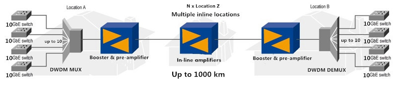
Case Four: If the distance of 400 km still cannot meet our requirement, we can set up more repeater sites to place other optical in-line amplifiers. At present, using these three kinds of EDFA amplifiers already enables 100Gbps bandwidth for realizing up to 1000 km in a point-to-point connection, as shown in the figure below.
Conclusion
When designing a long-haul DWDM network for transmitting big data, EDFA amplifier is an ideal solution for current and future optical system which should be taken into consideration. It can be deployed at the transmitter side, the receiver side and any intermediate point along the DWDM long fiber link, as optical preamplifier, booster amplifier and in-line amplifier, for enhancing the signal power, thereby a long-haul transmission can be deployed.
Why Not Build a 10G CWDM Network for Higher Capacity?
Although the 40G and 100G technologies develop vigorously recent years to meet the increasing need of higher capacity, they are still not widely accepted and applied due to high deploying cost. Under this case, choosing to build a 10G network is always the first choice for most users. But except upgrading our system, what else can we do when the 10G network can’t offer enough capacity? To address this issue, telcom engineers and researchers suggest that we can deploy the 10G CWDM networks. With use of CWDM optical multiplexer, this solution offers a highly cost effective method to gain more capacity on the basis of 10G network. Let’s study the benefits of 10G CWDM network and its two basic common network infrastructures in details.
What Can We Benefit from 10G CWDM Network?
In contrast to 10G DWDM network, 10G CWDM network can neither offer so high data capacity nor transmit the signals so long. But on the other hand, 10G CWDM network is an easier-to-deploy and less expensive solution that can well serve for a wide range of optical applications. Let’s study the main benefits of 10G CWDM networks.
- It is possible to add connections for transmitting more data in 10G network, which makes the whole network load increasing from 10G to 40G or 100G possible.
- CWDM Mux Demux is the key component of 10G CWDM network. As a passive component, it doesn’t require extra power, which is an ideal option for deploying 10G CWDM network.
- Instead of upgrading system, deploying 10G CWDM network to get more capacity can saves a lot of money due to the economical 10G hardware and cheap passive CWDM Mux Demux.
Understanding Common 10G CWDM Network Infrastructures
10G CWDM system is a passive optical network, which supports 10G transmission with any protocol over the optical link, as long as the 10G signals are at the specific CWDM wavelengths. At present, there are two common CWDM network infrastructures. One is 10G CWDM point-to-point network, and the other is 10G CWDM ring network. The following will introduce the two common infrastructures in details.
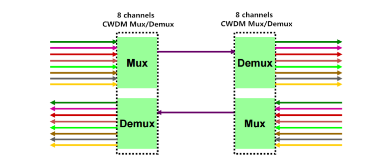
10G CWDM Point-to-Point Network: it is the simplest network infrastructure of the CWDM networks. As shown in the following figure, there are two passive CWDM Mux Demux deployed in the 10G network that offers 8 channels to multiplex the signals from 8 different optical fiber link into an integrated signal. Thereby, the signal can be transmit through only one fiber, which means there are 7 virtual fiber created with higher capacity for transmitting more data. As for the cheap passive CWDM Mux Demux, it can be available at very good price that costs less than upgrading the system from 10G to 40G or 100G. Undoubtedly, deploying a 10G CWDM point-to-point network is very economical solution for higher capacity.
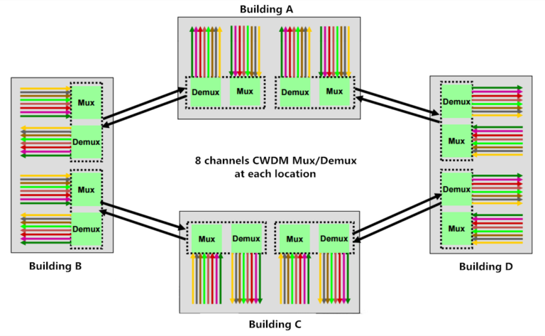
10G CWDM Ring Network: it is deployed on the basis of 10G CWDM point-to-point network. Compared to point-to-point network, the ring network is much more complex that needs other optical CWDM components like CWDM OADM. By adding CWDM OADM, two or more point-to-point network can be connected together, which can finally achieve a 10G CWDM ring network. To better understand how does the 10G CWDM ring network work, here offer a figure that shows four buildings are connected by several 8 channels CWDM Mux Demux and CWDM OADM for your reference.
Conclusion
Unlike upgrading the network from 10G to 40G or 100G, building a 10G CWDM network doesn’t requires changing all the network equipment which may cost highly. It only need CWDM transceiver and CWDM Mux Demux to be deployed in the original 10G network. For a complex 10G CWDM network, additional optical equipment like CWDM OADM are required. If you come across the capacity-hungry issue, building a 10G CWDM network would be a nice option for higher capacity.
Although the 40G and 100G technologies develop vigorously recent years to meet the increasing need of higher capacity, they are still not widely accepted and applied due to high deploying cost. Under this case, choosing to build a 10G network is always the first choice for most users. But except upgrading our system, what else can we do when the 10G network can’t offer enough capacity? To address this issue, telcom engineers and researchers suggest that we can deploy the 10G CWDM networks. With use of CWDM optical multiplexer, this solution offers a highly cost effective method to gain more capacity on the basis of 10G network. Let’s study the benefits of 10G CWDM network and its two basic common network infrastructures in details.
What Can We Benefit from 10G CWDM Network?
In contrast to 10G DWDM network, 10G CWDM network can neither offer so high data capacity nor transmit the signals so long. But on the other hand, 10G CWDM network is an easier-to-deploy and less expensive solution that can well serve for a wide range of optical applications. Let’s study the main benefits of 10G CWDM networks.
- It is possible to add connections for transmitting more data in 10G network, which makes the whole network load increasing from 10G to 40G or 100G possible.
- CWDM Mux Demux is the key component of 10G CWDM network. As a passive component, it doesn’t require extra power, which is an ideal option for deploying 10G CWDM network.
- Instead of upgrading system, deploying 10G CWDM network to get more capacity can saves a lot of money due to the economical 10G hardware and cheap passive CWDM Mux Demux.
Understanding Common 10G CWDM Network Infrastructures
10G CWDM system is a passive optical network, which supports 10G transmission with any protocol over the optical link, as long as the 10G signals are at the specific CWDM wavelengths. At present, there are two common CWDM network infrastructures. One is 10G CWDM point-to-point network, and the other is 10G CWDM ring network. The following will introduce the two common infrastructures in details.
10G CWDM Point-to-Point Network: it is the simplest network infrastructure of the CWDM networks. As shown in the following figure, there are two passive CWDM Mux Demux deployed in the 10G network that offers 8 channels to multiplex the signals from 8 different optical fiber link into an integrated signal. Thereby, the signal can be transmit through only one fiber, which means there are 7 virtual fiber created with higher capacity for transmitting more data. As for the cheap passive CWDM Mux Demux, it can be available at very good price that costs less than upgrading the system from 10G to 40G or 100G. Undoubtedly, deploying a 10G CWDM point-to-point network is very economical solution for higher capacity.
10G CWDM Ring Network: it is deployed on the basis of 10G CWDM point-to-point network. Compared to point-to-point network, the ring network is much more complex that needs other optical CWDM components like CWDM OADM. By adding CWDM OADM, two or more point-to-point network can be connected together, which can finally achieve a 10G CWDM ring network. To better understand how does the 10G CWDM ring network work, here offer a figure that shows four buildings are connected by several 8 channels CWDM Mux Demux and CWDM OADM for your reference.
Conclusion
Unlike upgrading the network from 10G to 40G or 100G, building a 10G CWDM network doesn’t requires changing all the network equipment which may cost highly. It only need CWDM transceiver and CWDM Mux Demux to be deployed in the original 10G network. For a complex 10G CWDM network, additional optical equipment like CWDM OADM are required. If you come across the capacity-hungry issue, building a 10G CWDM network would be a nice option for higher capacity.